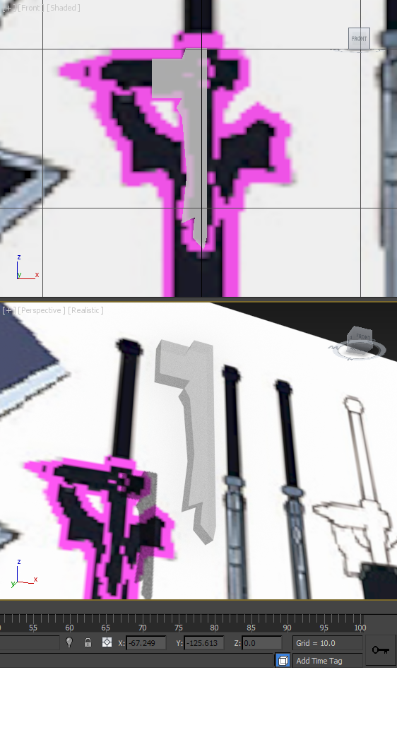
Modelling - Day 1Before I started modelling, I imported the template I found online then quickly realised I couldn't see the difference between the silver outline and the white background through the see-through model. As such, I took this image into Photoshop, selected all the silver outlines and coloured them a bright pink, making them extremely visible within 3DS Max through see-through models.
As I began to model, I decided to start at the guard to get my mind into gear by starting with a part of a medium level of difficulty. First of all, I identified that the blade and hilt/guard were two different parts, with the blade slotting inside the guard, as it is a thinner piece. I next realised that the guard isn't symmetrical so I can't simply use the 'Mirror Modifier' to mirror the part for each side. This meant I had to design the central part and leave the base as a square block before mirroring. I set out by extruding the block and adding lines to the face so that I had more vertices to manipulate. I used these to set out the basic shape of the part. I also added vertices where the centre of a curved edge was going to go. |
|
|
Modelling - Day 2
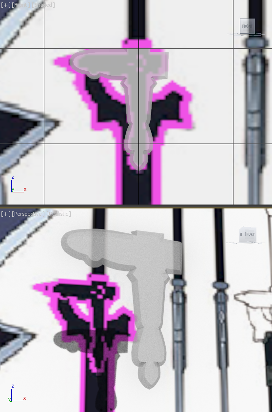
After I mirrored the design, I then worked off of each square block and sculptured each side's unique design. After I was happy with the basic shape, I used the 'Chamfer' tool to add the curves on the lines that I purposely added beforehand to curve the shape of the model exactly how I wanted. This sometimes required me to have multiple curve origin lines around the one curved edge, just so I could get the right kind of bend that I wanted. You can clearly see an example of this, that being the circular left edge of the left side of the guard.
After achieving the curves, I needed to round all the edges to a point. I did this by extruding all the sides, then scaling all of the outer vertices so that the front and back vertices overlapped. I then welded them together and played around with the placement until I was happy with the result.
After achieving the curves, I needed to round all the edges to a point. I did this by extruding all the sides, then scaling all of the outer vertices so that the front and back vertices overlapped. I then welded them together and played around with the placement until I was happy with the result.
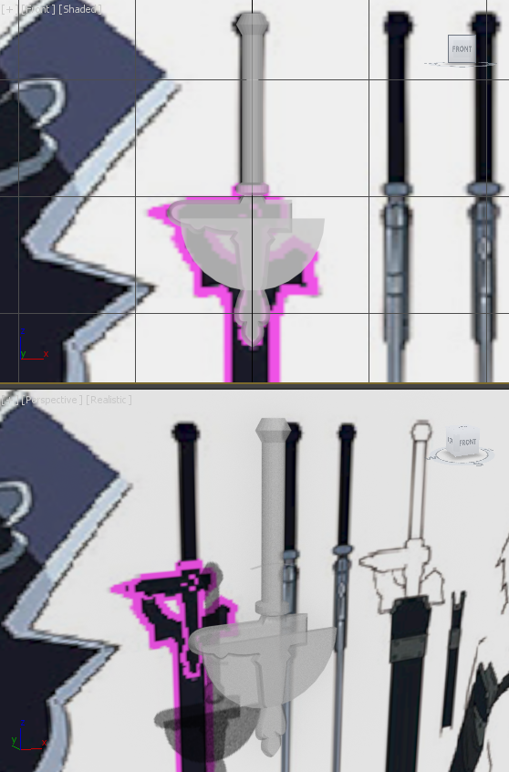
Modelling - Day 3On day 3, as I had finished the guard, I moved onto the hilt. This was a rather simply part to design, but involved a new trick I hadn't used yet. First, I extruded the top square out then I selected each vertical edge. From there I used a chamfer to turn the shape into an octagon shaped cylinder. I then did this a couple more times, until I ended up with a perfectly smooth cylinder that was attached to the guard.
From there it was simple; I just just extruded out that part, added more lines using the 'Connect' tool and then moved these looping lines around. After scaling them, I created the ring in between the hilt and the guard, as well as the pommel on the end of the hilt. As I still had time, I started to figure out how I would create the base of the blade. This part is like a doughnut right was cut up unequally, whilst having spiky horns and a long blade that comes out of it. I thought I'd start by creating a flat spherical cylinder, then splitting that in two to make a semi-circle. That's all I could do by the end of that session, so I carried on with the blade the next day. |
|
|
Modelling - Day 4
I actually ended up scrapping the semi-circle I had previously created and made a new circle disk, with a different number of sides. I then created a second duplicate disk and scaled this down. After subtracting this second disk from the first to create the inner hole, I removed the top half I didn't need and marked where the break would be on the right side using the 'Connect' tool, matching the template. After capping the hole made by removing these sections, I started to move the edge vertices around to create the three spikes.
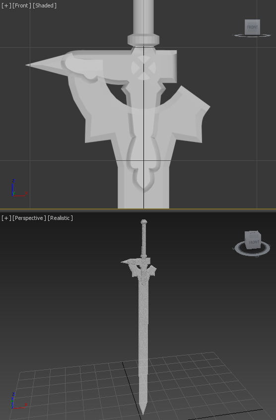
After I was happy with their shape, I selected the bottom four faces of the disk and extruded these down to create the full of the blade. After I brought the bottom corner vertices together and welded them to create the point, I then had to create the pointed edges on all the sides of the blade. I did this just the same as the guard, by extruding out each edge and then scaling all the outer front and back vertices so that they over lapped before welding them together.
After I was happy with their shape, I selected the bottom four faces of the disk and extruded these down to create the full of the blade. After I brought the bottom corner vertices together and welded them to create the point, I then had to create the pointed edges on all the sides of the blade. I did this just the same as the guard, by extruding out each edge and then scaling all the outer front and back vertices so that they over lapped before welding them together.
Modelling - Day 5On day 5, all I still needed to do was add the circular 'X' mark in the middle of the guard and texture everything in. Creating this circular 'X' shape was much harder than I thought. I took me a long time until I realised how to cut up the disk shaped cylinder I created to form the 'X' breaks in it. I first tried using the 'Slice Plane' tool, moving the origin of the sliding plane around to cut up each part, but finding the centre of the circle was made impossible after just a single slice.
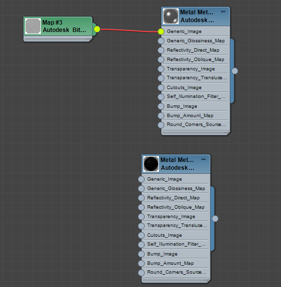
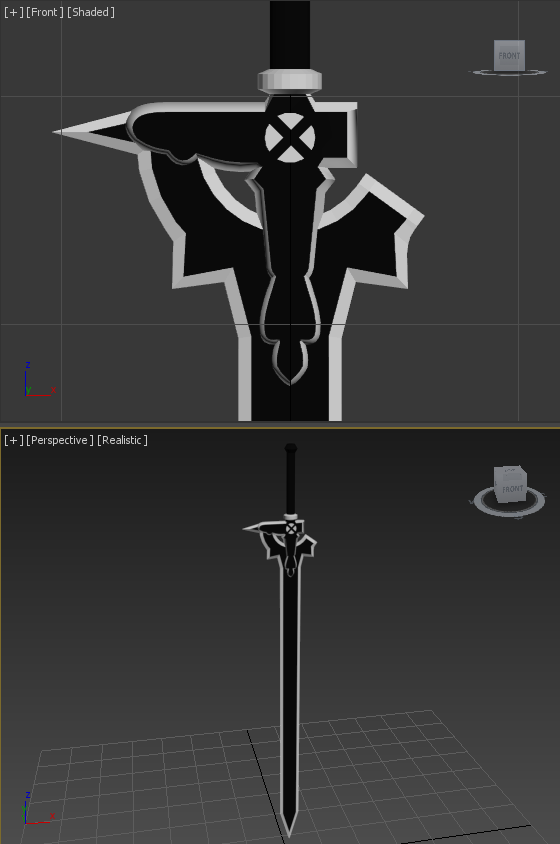
I researched online for another method and found out I could use the 'Pro Cutter' tool under the 'Compound Objects' drop-down menu in the 'Create' tab. First, I had to create multiple planes that I would use for slicing up the circle. This was much easier to do symmetrically as I could use world co-ordinates to position the planes. After applying the 'Pro Cutter' tool to the circular disk, using the cutting planes I created, I deleted the inner parts I didn't want. Finally, now that I had finished everything I merged them all together. Texturing - Day 6When texturing this model, it wasn't all that hard as there are only two different colours used in the original artwork. To mark out which part I wanted which colour I went through all the face ID numbers and made all the parts I wanted silver as ID 1 and all the parts I wanted black as ID 2. I selected all the faces with ID 1 and went into the Material Editor. In there I set the faces with ID 1 to the Metal, Metal Joints, Steel material, then select all the faces with ID 2 and set their texture to Metal, Metal 2400F Hot, selecting an extremely dark black material, that was just one shade lighter than full black. This was all I needed to match the textures of the model to the original sword's colouring in the anime/manga/light novels.
|
|
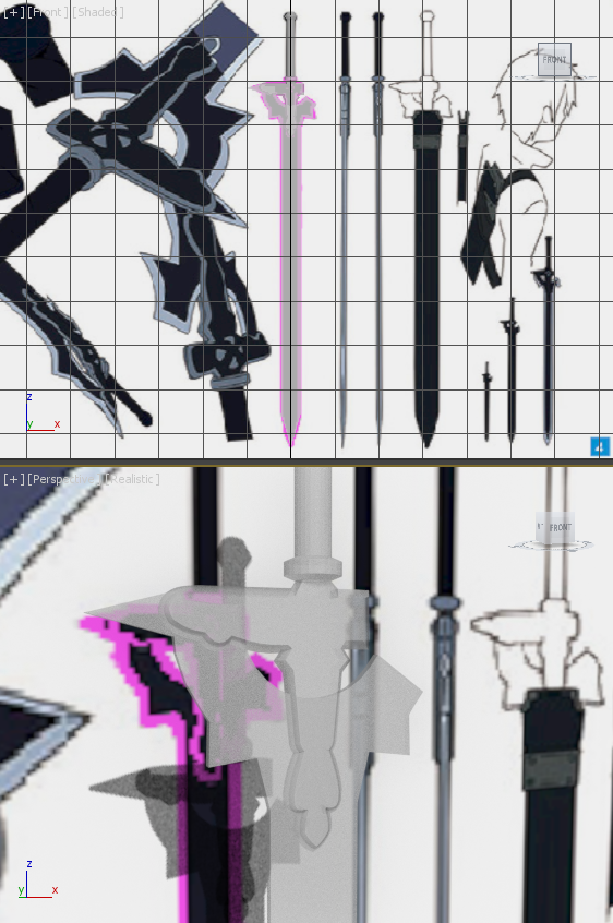
Final Image, 3D Viewer & Thoughts
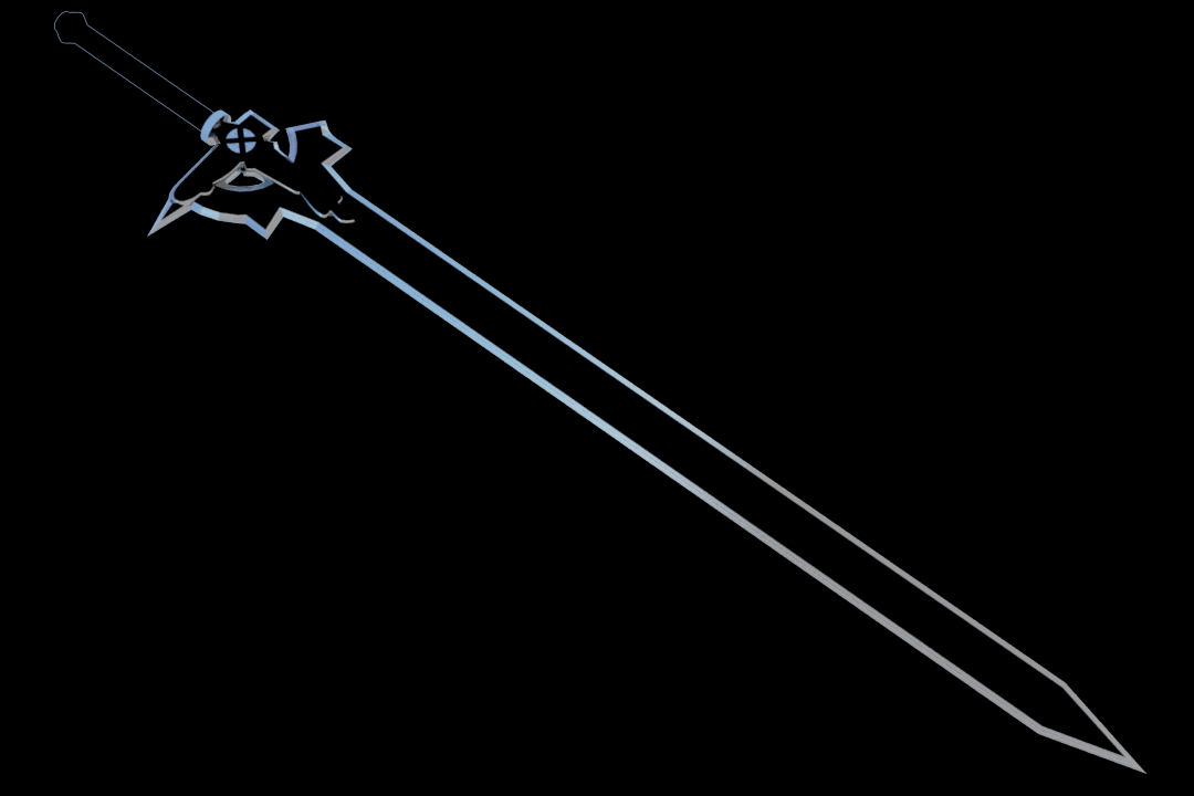
All and all I'm really happy with this model. It ended up taking much longer than I thought, but that's to be expected as this was my first model I made that wasn't just me following a tutorial video.
I ended up not creating the sheath for the sword as that would have been unnecessary and would have taken too long. I think this model is absolutely fine without it's sheath. If I was to re-do this I don't think there'd be anything I would change.
I ended up not creating the sheath for the sword as that would have been unnecessary and would have taken too long. I think this model is absolutely fine without it's sheath. If I was to re-do this I don't think there'd be anything I would change.
|
|